Product Details
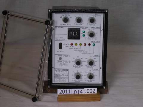
RMS 2V162K4 Transformer tap changer control (VOLTAGE REGULATOR RELAY)
4870
CASH
1 unit
Indonesia
INDEX 1. BROAD DESCRIPTION 1.1 Basic Functional Operation 1.2 Line Drop Compensator 2. SPECIFICATION 2.1 Power Supply 2.2 Voltage Sensing Circuitry 2.3 Line Drop Compensation (LDC) 2.4 Timers & Logic 2.5 Alarms 2.6 Alarms and Control Output Relays 2.7 Insulation Withstand 3. TEST EQUIPMENT REQUIRED 4. ASSOCIATED DRAWINGS 5. HIGH VOLTAGE TESTING 6. CALIBRATION & TEST PROCEDURE 6.1 Power Supply 6.2 Line Drop Compensation 6.3 Input Voltage Transformer Calibration 6.4 Average Detector Calibration 6.5 Reference Voltage Calibration 6.6 Undervoltage Calibration 6.7 Overvoltage Alarm Calibration 6.8 Error Detector Calibration 6.9 Initial Raise / Lower Timer Calibration 6.10 Calibration of Tap Change Interval Timer 6.11 Calibration of Auto Raise / Lower Control Pulse 6.12 Tapchanger Failure Alarm Timer 7. GENERAL & FUNCTIONAL 7.1 Operation of Logic Circuitry 7.2 LDC Operational Check 7.3 General 8. CONNECTION DIAGRAM 165-162-904 Issue I 21/05/1998 Sheet 3 of 12 1. BROAD DESCRIPTION 1.1 Basic Functional Operation The 2Vl62 continuously monitors the transformer output voltage and current. Voltages proportional to the current and having definite phase relationships with it (according to the external wiring configuration and line characteristics) are subtracted from the monitored voltage to give a replica of the Load Centre voltage. The corrected sensed voltage is rectified and smoothed to give a proportional DC voltage, which is subtracted from a DC reference proportional to the thumbwheel switch "Set Voltage" setting. If the magnitude of the error voltage exceeds a value determined by the "Sensitivity Setting", a "Raise" or "Lower" LED lights, according to the polarity of the error voltage. The" Initial Raise/Lower" timer is also initiated, and if the error persists for the duration of this timer setting, an operation of the appropriate output relay will occur. If the resultant tap change fails to bring the corrected sensed voltage to the desired value, a "Tap Change Interval" timer is initiated, and after this time has elapsed, a further tap change will take place. This last cycle will be repeated until the corrected sensed voltage is within the desired bandwidth, when both timers will be reset. The “Raise” and “Lower” output relays remain energised only in the time interval between initiation of the tap change and subsequent opening of the normally closed Tap Changer auxiliary contacts. 1.2 Line Drop Compensation Line Drop Compensation is used to enable the voltage at the source end of the transmission line to be adjusted to compensate for the Line voltage drop, and therefore achieve the required voltage at the load end of the Line, independent of the load current. To achieve this, the Line voltage at the source is sensed and a voltage proportional to the Line drop is subtracted from it. The resultant voltage is sensed by the electronic circuitry and a Tap changer is operated until the resultant derived Load voltage equals the voltage indicated on the Set Voltage thumbwheel switches. 2. SPECIFICATION 2.1 Power Supply Auxiliary Supply Range 40V to 275V AC 40V to 350V DC Auxiliary Supply Burden (Continuous) Less than 10VA Peak Inrush Current 3A at 40V AC RMS Inrush Current (Fully loaded) 40VA Ambient Temperature Range -5 to 55 deg C Input Transients Withstands multiple high-energy transients and ring waves in accordance with IEE28 -ANSI C26.1 category 11, accordingly: Ring wave 0.5uS 100KHz 6KV, 500A S/C, 4J Surge voltage 1.2/50uS 6KV O/C Surge current 8/20uS 3KA S/C, 80J clamped at 1000V EMI Noise Mains conducted EMI within limits specified by AS 3584 Class B 165-162-904 Issue I 21/05/1998 Sheet 4 of 12 2.1 Power Supply (Cont) Electrical Isolation The outputs are isolated from the input in accordance with AS 3260 class 11 Limited Current Circuit, accordingly: Withstand voltage of 2.5KV RMS 50Hz for one minute. Creepage and clearance distance greater than 4mm. Output leakage current less than 0.25mA to earth. Power Supply Fail Alarm Relay Normally closed contact rated at 250V AC and isolated as per AS 3260 are energised when both the input auxiliary supply and internal +24V DC rail is within acceptable limits. The relay will drop out causing an alarm output if either supply fails. 2.2 Voltage Sensing Circuitry Nominal Sensing Voltage 110 or 63.5 (tapped) Sensing Supply Burden Less than 1VA Nominal Sensing Frequency 50Hz ± 2Hz Regulated Voltage Setting Range 100 - 129.5 Volts (0.5V steps) Precision of Voltage Setting ± 0.5 Volt 2.3 Line Drop Compensation (LDC) Nominal Sensing Current 1 Amp or 5 Amp (tapped CT) CT Burden Less than 0.25VA Maximum Sensing Current 5 x nominal continuous, 20 x nominal for 3 seconds Resistance Compensation setting Range 0 - 20 Volts Accuracy ± 0.5V Reactance Compensation setting Range 0 - 20 Volts Accuracy ± 0.5V LDC Connection Mode Pos/Neg X, In-phase/Quad via front panel switch. Raise / Lower Comparator Sensitivity 0.5 to 3.0 Volts (continuously adjustable) Hysteresis 50% of error voltage (Other values may be specified) 2.4 Timers & Logic Initial Raise/Lower Timer 20 - 260 sec ± 5% of full-scale Norm/Inverse Mode switch on front panel. T = Tset x Vsense setting/Verror Inverse timing curve True inverse Tap Change Interval Timer 5 - 65 sec ± 5% of full scale “Raise” Output 1 N/O relay contact “Lower” Output 1 N/O relay contact 2.5 Alarms Under voltage Lockout 70 to 100 Volts (continuously adjustable). Hysteresis Approximately 95 % Relay contacts: 1 C/O provided Over voltage Alarm I00 to 130 Volts (continuously adjustable). Hysteresis Approximately 95 % Relay contacts: 1 C/O provided 165-162-904 Issue I 21/05/1998 Sheet 5 of 12 2.5 Alarms (Cont) Tapchanger Fail Alarm Timer 5 min ± 10% Auxiliary/Internal Supply Fail 1N/C relay contact 2.6 Alarm & Control Output Relays Type: Idec RHl B Contact Ratings 10A 24V DC resistive 0.5A 256V DC L/R 40 ms 2.7 Insulation Withstand 5KV 1/50us Impulse (coil to contacts) 1KV RMS across open contacts 3. TEST EQUIPMENT REQUIRED 110V 50Hz adjustable supply 5A Phase-adjustable current source 50V DC current- limited power supply Frequency/period counter Digital Voltmeter (4 1/2 digit preferable) DC Auxiliary Supply Electronic Counter HV Test Equipment 4. ASSOCIATED DRAWINGS 165-162-204 Circuit Schematic Diagram 660-272-301 Main Circuit Loading Diagram 660-258-301 Front Panel Loading Diagram 678-028-201 Power Supply Circuit Diagram 678-028-301 Power Supply Loading Diagram 5. HIGH VOLTAGE TESTING CLASS III Circuit Tests (5KV 1/50 and 2KV RMS) a) Apply 2KV RMS 50Hz between terminal groups 1 and 2 in table 1 below for 1 minute. b) Apply three 5KV 1/50us pulses of each polarity between terminal groups 1 and 2 in Table 1 below. TABLE 1 TEST GROUP 1 GROUP 2 A 8,9,22,23,24,25,26,27,28,29,30, (Inputs) 1,2,3,4,5,6,7,10,11,12,13,14,15,1 6,17,18,31,32, (Outputs) B All terminals excluding 5,6 & 7 connected together Earth (Frame)
© 2026 Copyright PT. Quinratu Karya Prisma by arFha. Page generated in 0.0057 seconds.