Product Details
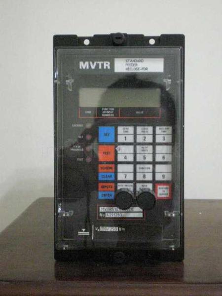
SEG RELAY MR13-IRSR and SEG RELAY MR13-IE
Negotable
Transfer, Cash
1
MRI3 - Digital multifunctional relay for overcurrent protection
2 TD_ MRI3_ 11.07_ GB
Contents
1 Introduction and application
2 Features and characteristics
3 Design
3.1 Connections
3.1.1 Analog input circuits
3.1.2 Output relays
3.1.3 Blocking input
3.1.4 External reset input
3.2 Relay output contacts
3.2.1 Fault recorder
3.2.2 Parameter settings ( see chapter 5)
3.3 LEDs
4 Working principle
4.1 Analog circuits
4.2 Digital circuits
4.3 Directional feature
4.3.1 Reversal in direction during the activation
phase
4.4 Earth fault protection
4.4.1 Generator stator earth fault protection
4.4.2 System earth fault protection
4.5 Earth-fault directional feature
( ER/ XR-relay type)
4.6 Determining earth short-circuit fault
direction
4.6.1 Directly earthed system
4.6.2 Resistance earthed system
4.6.3 Connection possibilities of the voltage
transformers for SR relay types
4.7 Demand imposed on the main current
transformers
5 Operation and settings
5.1 Display
5.2 Setting procedure
5.3 System parameter
5.3.1 Display of measuring values as primary
quantities ( Iprim phase)
5.3.2 Display of earth current as primary quantity
( Iprim earth)
5.3.3 Display of residual voltage UE as primary
quantity ( Uprim/ Usec)
5.3.4 Voltage transformer connection for residual
voltage measuring ( 3pha/ e-n/ 1: 1)
5.3.5 Nominal frequency
5.3.6 Display of the activation storage
( FLSH/ NOFL)
5.3.7 Parameter switch/ external triggering of the
fault recorder
5.4 Parameter protection
5.4.1 Pickup current for phase overcurrent
element ( I> )
5.4.2 Time current characteristics for phase
overcurrent element ( CHAR I> )
5.4.3 Trip delay or time factor for phase
overcurrent element ( tI> )
5.4.4 Reset setting for all tripping characteristics
in the phase current path
5.4.5 Current setting for high set element ( I> > )
5.4.6 Trip delay for high set element ( tI> > )
5.4.7 Relay characteristic angle RCA
5.4.8 Pickup value for residual voltage UE
( ER/ XR-relay type)
5.4.9 Pickup current for earth fault element ( IE> )
5.4.10 WARN/ TRIP changeover
( E/ X and ER/ XR-relay type)
5.4.11 Time current characteristics for earth fault
element ( CHAR IE) ( not for ER/ XR-relay
type)
5.4.12 Trip delay or time multiplier for earth fault
element ( tIE> > )
5.4.13 Reset mode for inverse time tripping in
earth current path
5.4.14 Current setting for high set element of
earth fault supervision ( IE> > )
5.4.15 Trip delay for high set element of earth
fault supervision ( tIE> > )
5.4.16 COS/ SIN Measurement
( ER/ XR-relay type)
5.4.17 SOLI/ RESI changeover ( SR-relay type)
5.4.18 Block/ Trip time
5.4.19 Circuit breaker failure protection tCBFP
5.4.20 Adjustment of the slave address
5.4.21 Setting of Baud-rate ( applies for Modbus
Protocol only)
5.4.22 Setting of parity ( applies for Modbus
Protocol only)
5.5 Fault recorder
5.5.1 Adjustment of the fault recorder
5.5.2 Number of the fault recordings
5.5.3 Adjustment of trigger occurrences
5.5.4 Pre-trigger time ( Tpre)
5.6 Adjustment of the clock
5.7 Additional functions
5.7.1 Blocking the protection functions and
assignment of the output relays
5.8 Setting value calculation
5.8.1 Definite time overcurrent element
5.8.2 Inverse time overcurrent element
5.9 Indication of measuring and fault values
5.9.1 Indication of measuring values
5.9.2 Units of the measuring values displayed
5.9.3 Indication of fault data
5.9.4 Fault memory
5.10 Reset
5.10.1 Erasure of fault storage
TD_ MRI3_ 11.07_ GB 3
6 Relay testing and commissioning
6.1 Power-On
6.2 Testing the output relays and LEDs
6.3 Checking the set values
6.4 Secondary injection test
6.4.1 Test equipment
6.4.2 Example of test circuit for MRI3 relays
without directional feature
6.4.3 Checking the input circuits and measured
values
6.4.4 Checking the operating and resetting
values of the relay
6.4.5 Checking the relay operating time
6.4.6 Checking the high set element of the relay
6.4.7 Example of a test circuit for MRI3 relay
with directional feature
6.4.8 Test circuit earth fault directional feature
6.4.9 Checking the external blocking and reset
functions
6.4.10 Testing the external blocking with
Block/ Trip function
6.4.11 Test of the CB failure protection
6.5 Primary injection test
6.6 Maintenance
7 Technical data
7.1 Measuring input circuits
7.2 Common data
7.3 Setting ranges and steps
7.3.1 Time overcurrent protection ( I-Type)
7.3.2 Earth fault protection ( SR-Type)
7.3.3 Earth fault protection ( E/ X-Type)
7.3.4 Earth fault protection ( ER/ XR-Type)
7.3.5 Block/ Trip time
7.3.6 Switch failure protection
7.3.7 Interface parameter
7.3.8 Parameter for the fault recorder
7.3.9 Inverse time overcurrent protection relay
7.3.10 Direction unit for phase overcurrent relay
7.3.11 Determination of earth fault direction
( MRl3-ER/ XR)
7.3.12 Determination of earth fault direction
( MRl3-SR)
7.4 Inverse time characteristics
7.5 Output contacts
8 Order form
4 TD_ MRI3_ 11.07_ GB
1 Introduction and application
The MRl3 digital multifunctional relay is a universal
time overcurrent and earth fault protection device intended
for use in medium-voltage systems, either with
an isolated/ compensated neutral point or for networks
with a solidly earthed/ resistance-earthed neutral point.
The protective functions of MRI3 which are implemented
in only one device are summarized as follows:
Independent ( Definite) time overcurrent relay,
inverse time overcurrent relay with selectable characteristics,
integrated determination of fault direction for application
to doubly infeeded lines or meshed systems,
two-element ( low and high set) earth fault protection
with definite or inverse time characteristics,
integrated determination of earth fault direction for
application to power system networks with isolated
or arc suppressing coil ( Peterson coil) neutral
earthing. ( ER/ XR-relay type) ,
integrated determination of earth short-circuit fault direction
in systems with solidly-earthed neutral point or
in resistance-earthed systems ( SR-relay type) .
Furthermore, the relay MRI3 can be employed as a
back-up protection for distance and differential protective
relays.
A similar, but simplified version of overcurrent relay
IRI1 with reduced functions without display and serial
interface is also available.
Important:
For additional common data of all MR-relays please
refer to manual " MR - Digital Multifunctional relays" .
On page 51 of this manual you can find the valid
software versions.
2 Features and characteristics
Digital filtering of the measured values by using discrete
Fourier analysis to suppress the high frequence
harmonics and DC components induced by faults or
system operations,
two parameter sets,
selectable protective functions between:
definite time overcurrent relay and
inverse time overcurrent relay,
selectable inverse time characteristics according to
IEC 255-4:
Normal Inverse ( Type A)
Very Inverse ( Type B)
Extremely Inverse ( Type C)
Special characteristics,
reset setting for inverse time characteristics selectable,
high set overcurrent unit with instantaneous or definite
time function,
two-element ( low and high set) overcurrent relay both
for phase and earth faults,
directional feature for application to the doubly infeeded
lines or meshed systems,
earth fault directional feature selectable for either isolated
or compensated networks,
sensitive earth fault current measuring with or without
directional feature ( X and XR-relay type) ,
determination of earth short-circuit fault direction for
systems with solidly-earthed or resistance-earthed
neutral point,
numerical display of setting values, actual measured
values and their active, reactive components, memorized
fault data, etc.,
display of measuring values as primary quantities,
withdrawable modules with automatic short circuiters
of C.T. inputs when modules are withdrawn,
blocking e.g. of high set element ( e.g. for selective
fault detection through minor overcurrent protection
units after unsuccessful AR) ,
relay characteristic angle for phase current directional
feature selectable,
circuit breaker failure protection,
storage of trip values and switching-off time ( tCBFP) of
5 fault occurences ( fail-safe of voltage) ,
recording of up to eight fault occurences with time
stamp,
free assignment of output relays
serial data exchange via RS485 interface possible;
alternatively with SEG RS485 Pro-Open Data Protocol
or Modbus Protocol,
suppression of indication after an activation
( LED flash) ,
display of date and time
TD_ MRI3_ 11.07_ GB 5
3 Design
3.1 Connections
Phase and earth current measuring:
Figure 3.1: Measuring of the phase currents for over-current- and
short-circuit protection ( I> , I> > )
Figure 3.2: Earth-fault measuring by means of ring-core C.T. ( IE)
When phase-- and earth-fault current measuring are
combined, the connection has to be realized as per
Figure 3.1and Figure 3.2 or Figure 3.3.
Figure 3.3: Phase current measuring and earth-current detection
by means of Holmgreen-circuit.
This connection can be used with three existing phase
current transformers when combined phase and earthcurrent
measuring is required.
Disadvantage of holmgreen-circuit:
At saturation of one or more C.Ts the relay detects
seeming an earth current.
* This arrow shows the current flow in forward direction, for this LED lights up green
6 TD_ MRI3_ 11.07_ GB
Voltage measuring for the directional detection:
Figure 3.4: Measuring of the phase voltages for the directional
detection at overcurrent, short-circuit or earth-fault
protection ( I> , I> > , IE> and IE> > ) .
For details on the connection of ER/ XR-unit type c.t.s,
see para 4.5.
I>
I>
I>
A3 L1
U1
U2
A5 L2
A7 L3
A2 N
U3
L1
L2
L3
a
b
c
Figure 3.5: Voltage transformer in V-connection for the
directional detection at overcurrent and short-circuit
protection.
The V-connection can not be applied at earth fault directional
feature.
3.1.1 Analog input circuits
The protection unit receives the analog input signals of
the phase currents IL1 ( B3-B4) , IL2 ( B5-B6) , IL3 B7-B8)
and the current IE ( B1-B2) , phase voltages U1 ( A3) ,
U2 ( A5) , U3 ( A7) with A2 as star point, each via
separate input transformers.
The constantly detected current measuring values are
galvanically decoupled, filtered and finally fed to the
analog/ digital converter.
For the unit type with earthfault directional features
( ER/ XR-relay type) the residual voltage UE in the secondary
circuit of the voltage transformers is internally
formed.
In case no directional feature for the phase current
path is necessary the residual voltage from the open
delta winding can directly be connected to A3 and
A2.
See Chapter 4.5 for voltage transformer connections
on isolated/ compensated systems.
3.1.2 Output relays
The MRI3 is equipped with 5 output relays. Apart from
the relay for self-supervision, all protective functions
can be optionally assigned:
Relay 1: C1, D1, E1 and C2, D2, E2
Relay 2: C3, D3, E3 and C4, D4, E4
Relay 3: C5, D5, E5
Relay 4: C6, D6, E6
Relay 5: Self-supervision C7, D7, E7
All trip and alarm relays are working current relays,
the relay for self supervision is an idle current relay.
3.1.3 Blocking input
The blocking functions adjusted before will be blocked
if an auxiliary voltage is connected to ( terminals)
D8/ E8. ( See chapter 5.7.1)
3.1.4 External reset input
Please refer to chapter 5.10.
TD_ MRI3_ 11.07_ GB 7
3.2 Relay output contacts
Figure 3.6
3.2.1 Fault recorder
The MRI3 is equipped with a disturbance value recorder
which records the measured analogue values
as momentary values. The momentary values
iL1, iL2, iL3, iE,
are scanned within a grid 1.25 ms ( with 50 Hz) or
1.041 ms ( with 60 Hz) and filed in a circulating storage.
The max. storage capacity amounts to 16 s ( with
50 Hz) or 13.33 s ( with 60 Hz) .
Storage division
Independent of the recording time, the entire storage
capacity can be divided into several cases of disturbance
with a shorter recording time each. In addition,
the deletion behaviour of the fault recorder can be influenced.
No writing over
If 2, 4 or 8 recordings are chosen, the complete
memory is divided into the relevant number of partial
segments. If this max. number of fault event has been
exceeded, the fault recorder block any further recordings
in order to prevent that the stored data are
written over. After the data have been read and deleted,
the recorder to ready again for further action.
Writing over
If 1, 3 or 7 recordings are chosen, the relevant number
of partial segments is reserved in the complete
memory. If the memory is full, a new recording will
always write over the oldest one.
The memory part of the fault recorder is designed as
circulating storage. In this example 7 fault records can
be stored ( written over) .
Memory space 6 to 4 is occupied.
Memory space 5 is currently being written in
Figure 3.7: Division of the memory into 8 segments, for example
Since memory spaces 6, 7 and 8 are occupied, this
example shows that the memory has been assigned
more than eight recordings. This means that No. 6 is
the oldest fault recording and No. 4 the most recent
one.
8 TD_ MRI3_ 11.07_ GB
trigger occurence
recording duration
Tpre
[ s]
Figure 3.8: Recording scheme of the fault recorder with
pre-trigger time
Each memory segment has a specified storage time
which permits setting of a time prior to the trigger
event.
Via the interface RS485 the data can be read and
processed by means of a PC with HTL/ PL-Soft4. The
data is graphically edited and displayed. Binary
tracks are recorded as well, e.g. activation and trip.
TD_ MRI3_ 11.07_ GB 9
3.2.2 Parameter settings ( see chapter 5)
System parameter
Relay type MRI3- I IE
IX
IRE
IRX
IR IER
IXR
IRER
IRXR
ER
XR
E
X
ISR IRSR SR
Display of measuring values as primary
quantities ( Iprim phase)
X X X X X X X X
Display of earth current as primary
quantities ( Iprim earth)
X X X X X X X X X
Display of residual voltage UE as primary
quantity ( Uprim/ Usec)
X X X
3pha/ e-n/ 1: 1 X X X
50/ 60 Hz X X X X X X X X X X X
LED-Flash X X X X X X X X X X X
RS 485/ Slaveaddress X X X X X X X X X X X
Baud-Rate 1) X X X X X X X X X X X
Parity-Check 1) X X X X X X X X X X X
Adjustment of the clock:
Y = year; M = month; D = day;
h = hour; m = minute; s = sec.
X X X X X X X X X X X
Table 3.1: System parameters of the different relay types
Protection parameter
Relay type MRI3- I IE
IX
IRE
IRX
IR IER
IXR
IRER
IRXR
ER
XR
E
X
ISR IRSR SR
2 parameter sets X X X X X X X X X X X
I> X X X X X X X X
CHAR I> X X X X X X X X
tI> X X X X X X X X
0 s/ 60 s 2) X X X X X X X X
I> > X X X X X X X X
tI> > X X X X X X X X
RCA X X X X
UE X X X
IE> X X X X X X X X X
warn/ trip X X X X X X
CHAR IE X X X X X X
tIE X X X X X X X X X
0s / 60 s 3) X X X X X X
IE> > X X X X X X X X X
tIE> > X X X X X X X X X
sin/ cos X X X
soli/ resi X X X
tCBFP X X X X X X X X X X X
Block/ Trip X X X X X X X X X X X
Table 3.2: Protection parameters of the different relay types.
1) Only devices with Modbus-Protocol
2) Reset setting for inverse time characteristics in phase current path
3) Reset setting for inverse time characteristics in earth current path
10 TD_ MRI3_ 11.07_ GB
Parameter for the fault recorder
Relay type MRI3- I IE
IX
IRE
IRX
IR IER
IXR
IRER
IRXR
ER
XR
E
X
ISR IRSR SR
Number of fault events X X X X X X X X X X X
Trigger events X X X X X X X X X X X
Pre-trigger time ( Tpre) X X X X X X X X X X X
Table 3.3: Parameters for the fault recorder of the different relay types
Additional parameters
Relay-type MRI3- I IE
IX
IRE
IRX
IR IER
IXR
IRER
IRXR
ER
XR
E
X
ISR IRSR SR
Blocking mode 1) X X X X X X X X X X X
Relay parameterizing X X X X X X X X X X X
Fault recorder X X X X X X X X
Table 3.4: Additional parameters of the different relay types
1) For 2 parameter sets ( separately for each parameter set)
TD_ MRI3_ 11.07_ GB 11
Figure 3.9: Front plate MRI3-I
Figure 3.10: Front plate MRI3-E/ X
Figure 3.11: Front plate MRI3-IR
Figure 3.12: Front plate MRI3-ER/ XR
12 TD_ MRI3_ 11.07_ GB
Figure 3.13: Front plate MRI3-SR
Figure 3.14: Front plate MRI3-IRER/ IRXR and MRI3-IER/ IXR
3.3 LEDs
The LEDs left from the display are partially bi-coloured,
the green indicating measuring, and the red fault indication.
MRI3 with directional feature have a LED ( green- and
red arrow) for the directional display. At pickup/ trip
and parameter setting the green LED lights up to indicate
the forward direction, the red LED indicates the
backward direction.
The LED marked with letters RS lights up during setting
of the slave address of the device for serial data communication.
The LEDs arranged at the characteristic points on the
setting curves support the comfortable setting menu selection.
In accordance with the display 5 LEDs for
phase fault overcurrent relay and 5 LEDs for earth-fault
relay indicate the corresponding menu point selected.
The LED labelled with the letters LR is alight while the
fault recorder is being adjusted.
Figure 3.15: Front plate MRI3-IRSR; MRI3-IRE/ IRX and MRI3-ISR
TD_ MRI3_ 11.07_ GB 13
4 Working principle
4.1 Analog circuits
The incoming currents from the main current transformers
on the protected object are converted to voltage
signals in proportion to the currents via the input transformers
and burden. The noise signals caused by inductive
and capacitive coupling are supressed by an
analog R-C filter circuit.
The analog voltage signals are fed to the A/ Dconverter
of the microprocessor and transformed to
digital signals through Sample- and Hold-circuits. The
analog signals are sampled at 50 Hz ( 60 Hz) with a
sampling frequency of 800 Hz ( 960 Hz) , namely, a
sampling rate of 1.25 ms ( 1.04 ms) for every measuring
quantity. ( 16 scans per periode) .
Figure 4.1: Block diagram
4.2 Digital circuits
The essential part of the MRI3 relay is a powerful microcontroller.
All of the operations, from the analog
digital conversion to the relay trip decision, are carried
out by the microcontroller digitally. The relay program
is located in an EPROM ( Electrically-Programmable-
Read-Only-Memory) . With this program the CPU of the
microcontroller calculates the three phase currents and
ground current in order to detect a possible fault situation
in the protected object.
For the calculation of the current value an efficient digital
filter based on the Fourier Transformation ( DFFT -
Discrete Fast Fourier Transformation) is applied to suppress
high frequency harmonics and DC components
caused by fault-induced transients or other system disturbances.
The calculated actual current values are compared
with the relay settings. If a phase current exceeds the
pickup value, an alarm is given and after the set trip
delay has elapsed, the corresponding trip relay is activated.
The relay setting values for all parameters are stored in
a parameter memory ( EEPROM - Electrically Erasable
Programmable Read-only Memory) , so that the actual
relay settings cannot be lost, even if the power supply
is interrupted.
The microprocessor is supervised by a built-in " watchdog"
timer. In case of a failure the watchdog timer resets
the microprocessor and gives an alarm signal, via
the output relay " self supervision" .
4.3 Directional feature
A built-in directional element in MRI3 is available for
application to doubly infeeded lines or to ring networks.
The measuring principle for determining the direction is
based on phase angle measurement and therefore
also on coincidence time measurement between current
and voltage. Since the necessary phase voltage
for determining the direction is frequently not available
in the event of a fault, whichever line-to-line voltage follows
the faulty phase by 90 is used as the reference
voltage for the phase current. The characteristic angle
at which the greatest measuring sensitivity is achieved
can be set to precede the reference voltage in the
range from 15 to 83 .
Figure 4.2: Relay characteristic angle
The TRIP region of the directional element is determined
by rotating the phasor on the maximum sensitivity
angle for 90 , so that a reliable direction decision
can be achieved in all faulty cases.
14 TD_ MRI3_ 11.07_ GB
4.3.1 Reversal in direction during the
activation phase
Reversal of the current direction during the activation
phase can lead to hyperfunctions. This mainly applies
to installations where parallel connected lines are
monitored by current relays with directional feature.
For this reason the directional determination for the
phase current is shown in a time window; this applies
to all SR
© 2026 Copyright PT. Quinratu Karya Prisma by arFha. Page generated in 0.0208 seconds.